25-Hour Digital Myst Clock/Chronometer
My wall clock in my house recently died, and with there being a running joke that I’m a time traveller thanks to my DeLorean, I thought I might as well build a replacement clock myself so it could be extra unique. Here’s what I came up with: a self-setting, self-correcting, self-adjusting wall clock/chronometer that tells time both in our timekeeping system and in the 25-hour D’ni timekeeping system used in the Myst series of video games. This is actually pretty handy if you want to know if it’s the right time to log in for certain events in Myst Online: Uru Live.

It tells you the time both in our “surface” time and in the D’ni cavern!
Technically it’s more a “chronometer” than a “clock” – the main difference between the two is that chronometers have far higher accuracy & precision, to the point that they can be used for scientific experiments. For this one, it’s generally safe to assume it shouldn’t read outside 0.003s of the actual time, but in practice it’s usually under 0.001s of the actual time. It’s no atomic clock, but it’ll do for most of my slow-mo needs. The whole project’s been designed to be as cheap, low-tech, skill-free, and expensive-tool-free as possible.
(Youtube Link in case the above video doesn’t work for you)
First up, a little primer – the digits used in the Myst games, aka D’ni digits, are a base-25 numbering system. This means they count up using symbols like [1], [2], [3], [4] … [22], [23], [24], [1][0]. That is, what they call “10”, we call “25” – the same way that in hexadecimal “10” represents what we call “16”. The numbers themselves are based on the numbers 0-4, which are then rotated anticlockwise 90° to represent 5/10/15/20. Here’s an example of D’ni numbers, showing how you add the row & column header symbols together to get the final number symbol:
Each D’ni “day”, or “yahr”, is roughly 30 hours, 14 minutes long and each D’ni “second”, or “prorahn”, is roughly 1.4 seconds. The Guild of Archivists has more details on how the actual D’ni timekeeping system works if that interests you. There’s nothing like these digits anywhere out there on the market, aside from something crazy like using LCD displays, but that didn’t interest me much and wouldn’t meet the goals of cheap or low-tech. So I had to come up with my own… And here’s how that turned out!
There’s so many places I could start with describing how this project was made so I’m gonna pick the one that probably interests most people reading this – the custom D’ni digit 25-segment displays! These are basically like my own custom 7-segment displays, but they’re easier to read with much higher contrast than store-bought 7-segs. I couldn’t find any instructions or guides out there on how to make your own (I’m sure there has to be some out there somewhere), so I had to work it all out myself from trial and error. The design itself was all made in Inkscape. Laser cutting holes in sheet acrylic and filling them with translucent resin was the way to go. The trickiest part is to have even light diffusion throughout an entire cell. The black parts are made from laser-cut 4.5mm black acrylic.

Laser-cutting D’ni digits out of acrylic
To help bounce light around inside each cell as much as possible, I airbrushed them with a thin white paint before filling them with resin. For the side that was to be the “front”, aka the good-quality side, I wanted the poured resin cells to be smooth & flush with the surface of the acrylic, which is tricky. I placed a piece of clear packing tape on a table with the sticky side up, stretched it out as far as I could, then carefully placed the front of the acrylic piece on the stretched tape. This kept the packing tape under constant tension, so that the resin cured against a smooth flat surface. The empty cells were filled with a 7:1 mixture of clear resin with super fine plaster of paris (mixed before pouring, obviously), which was the best-looking diffusing medium I tried. If you try this, sift the plaster into the resin while stirring to make it as evenly distributed as possible and to reduce plaster clumps in the resin. Use a needle to break up the remaining clumps and to remove any air bubbles that might be stuck in the corners. I recommend carefully picking up the cured acrylic blocks and looking at them from underneath to check for any plaster clumps or bubbles too. A vacuum chamber would be great if you’ve got one to remove the bubbles, but I didn’t have one. Once the resin was cured I carefully removed the packing tape and the segments were ready.
(Youtube Link in case the above video doesn’t work for you)
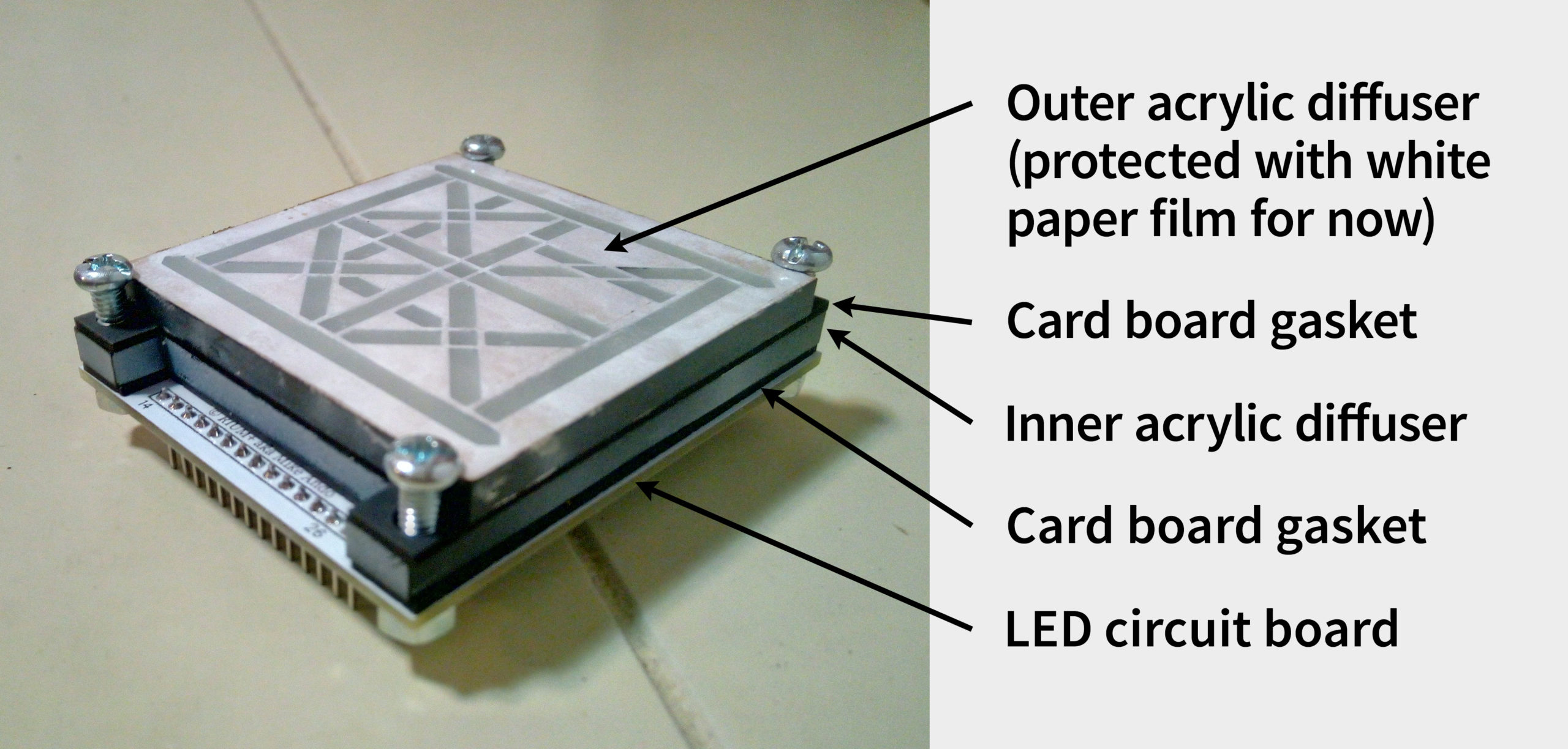
At 4.5mm thick, a single layer of diffusion from this material is likely good enough for most people, but just to make the light segments look extra smooth I used two layers of resin-filled acrylic. However, in this video you can see that there’s a lot of light bleeding from one cell to another, so to seal the edges well, I laser-cut some cardboard gaskets out of 2mm thick black cardboard backing board. I painted the interior edges with a silver pen to increase reflection. I used these gaskets between the two layers of acrylic as well as between the acrylic and the circuit board. I tried adding layers of proper light diffusion film between the gaskets, but they did so little and they would’ve been so fiddly to place in each cell that I didn’t bother.
The 5 layers in the 25-segment digital D’ni display modules – acrylic layers on the left, cardboard gaskets in the middle, circuit board on the right
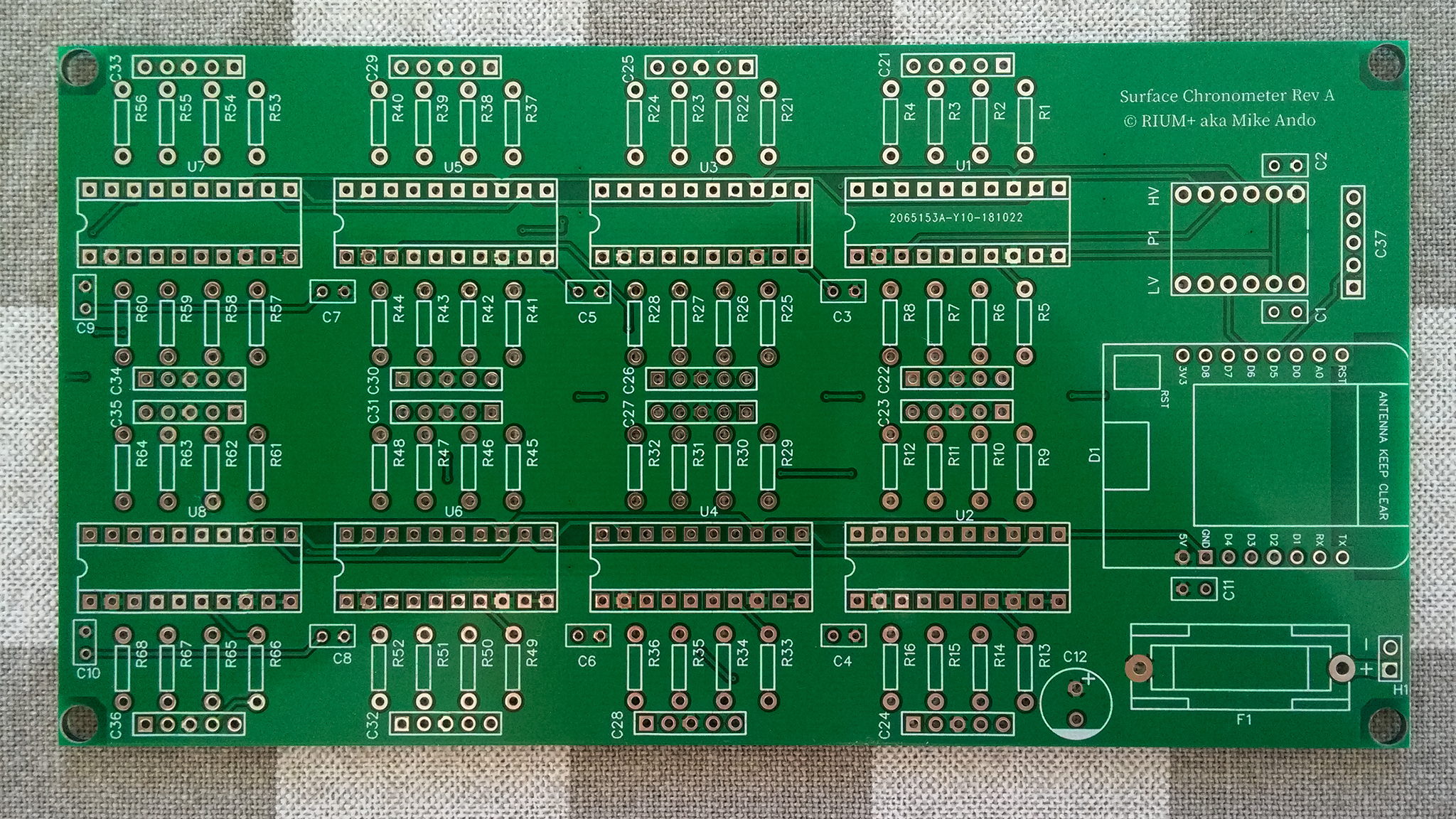
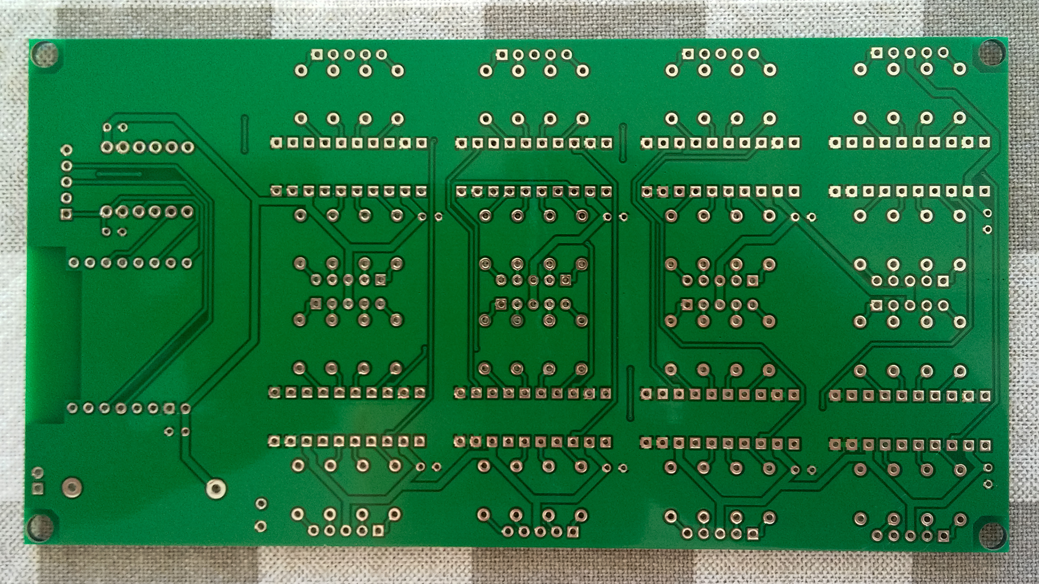
The custom circuit boards were all made in EasyEDA, which is simple enough to use that it runs in your web browser. The layout was imported from Inkscape’s SVG and I used that to properly position the LEDs. Each board has 50 individual LEDS in strings ranging from 1 LED to 4 LEDs long. There’s 36 discrete cells, or resin-filled holes in the acrylic, but some are always lit up together so there’s only 26 controllable segments. There were 2 different voltages used for these boards – 9 Volts for the strings of 4 & 3 LEDs, and 5 Volts for the strings of 2 & 1 LEDs.
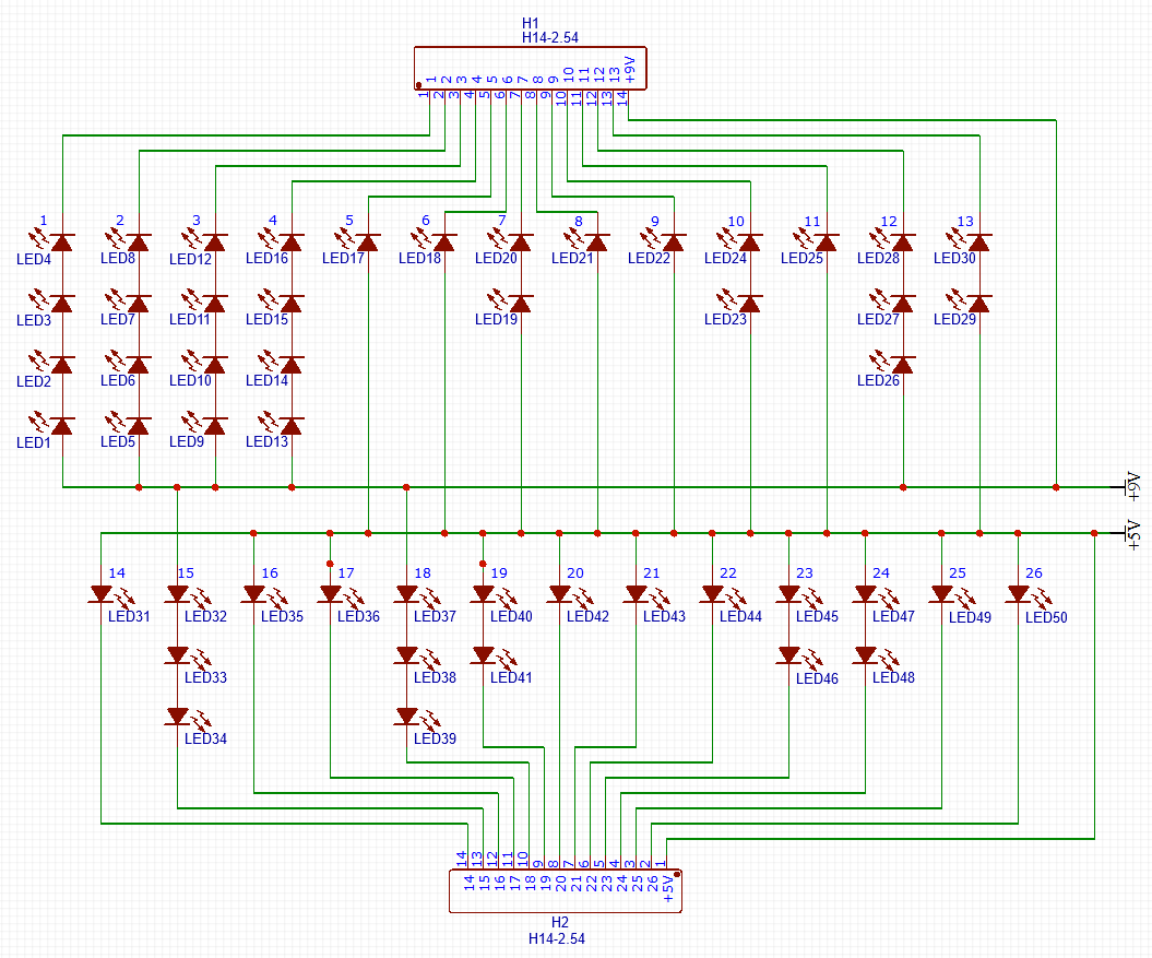
EasyEDA’s logic-level layout of the 25-segment D’ni Display
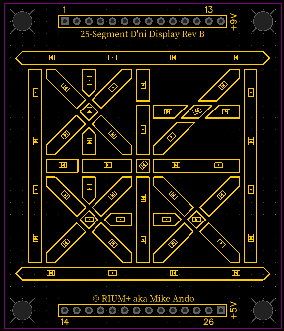
Silkscreen layout of the 25-segment D’ni Display
I know a lot of people like to rag on the autorouter feature of EDA software, but for something like this it works perfectly. Aside from a few starting obvious straight traces I put down myself, and a few extra links added right at the end to reduce the chances of the top or bottom planes acting like antennae, everything else was autorouted.
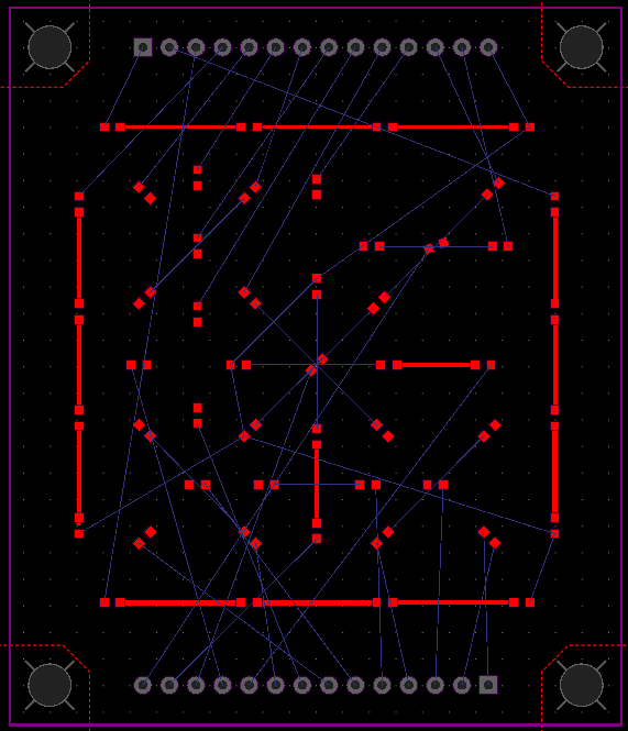
LEDs and a couple traces placed on the 25-segment D’ni Display circuit layout
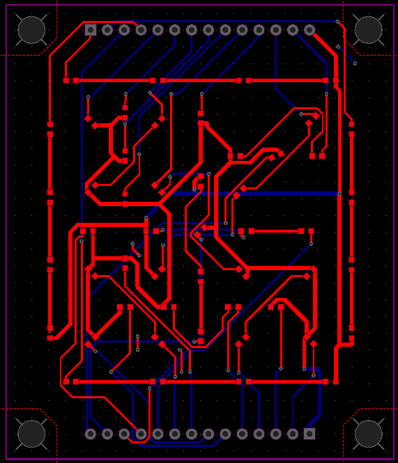
Final circuit layout of the 25-segment D’ni Display circuit, mostly autorouted – I didn’t draw this, it was automatically drawn for me
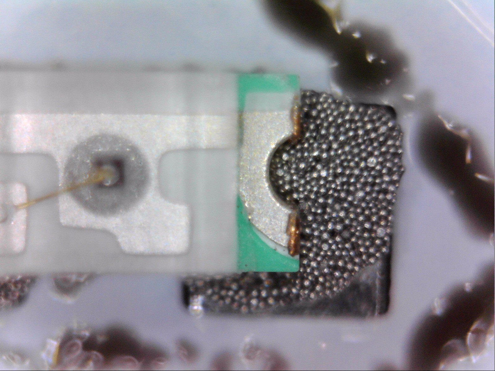
With so many tiny SMD LEDs needing soldering, I definitely recommend paying extra to order a solder stencil along with your circuit board. I have pretty shaky hands due to some medication I’m currently on, but I could manage placing them on the small pads of solder paste left by the stencils. It’s called solder paste but it’s easier to work with (and more accurate) if you think of it as a bunch of tiny beads in oil, rather than an actual paste. If you’ve ever wondered what solder paste looks like up close, here’s some microscope photos!


You can use a fancy reflow oven or an electronics hot plate to fuse the solder, but you can also just use a frying pan on a stove, so long as your pan is actually properly flat. Getting the right temperature is important so check with your brand of solder paste – I used Maker Paste which needs 140’C/284’F. Note that standard cheap IR spot thermometers won’t normally work on metal pans (the pan will reflect the IR light giving a wrong reading), but thermal cameras or cooking thermometers work. One clever hack is to add a few drops of water to the pan & count how long it takes for those drops to boil, add half of that time again, and you should be at around 140’C. Preheat the frying pan and the moment the paste all melts & goes shiny, remove the board from heat – this should take under 10 seconds.

Frying pans totally work as reflow ovens
Pro tip – you can use baking paper to help make it easier to pick up when you’re done, but make sure you use paper that’s rated for whatever temperature you’re using. This is what happens when you use cheap paper that’s not rated that high. Oops. Made a super pretty pattern, though.
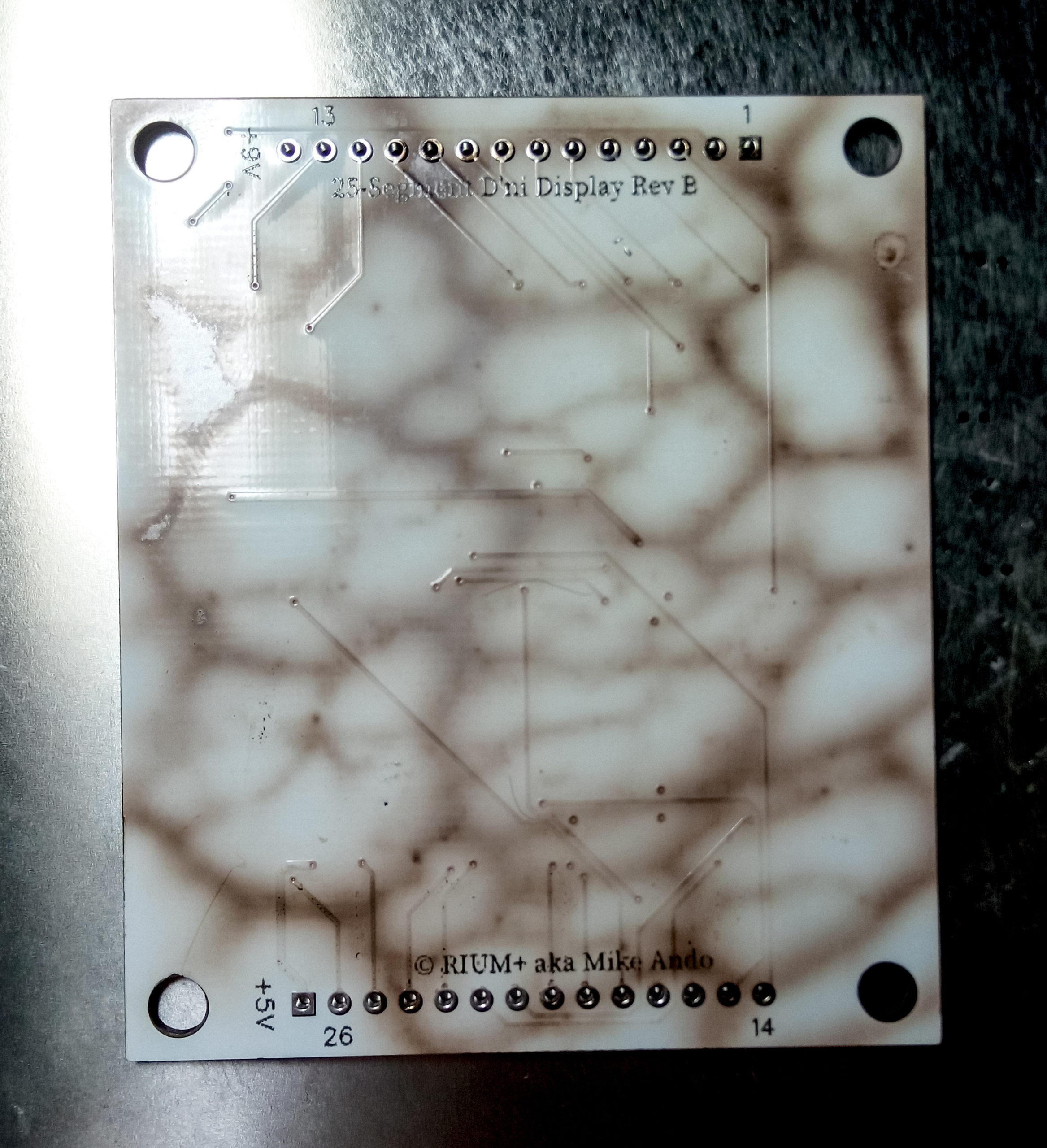
I asked a couple dozen people for guesses on what made this bubble-like burn pattern and no one guessed baking paper on fire. Go figure.
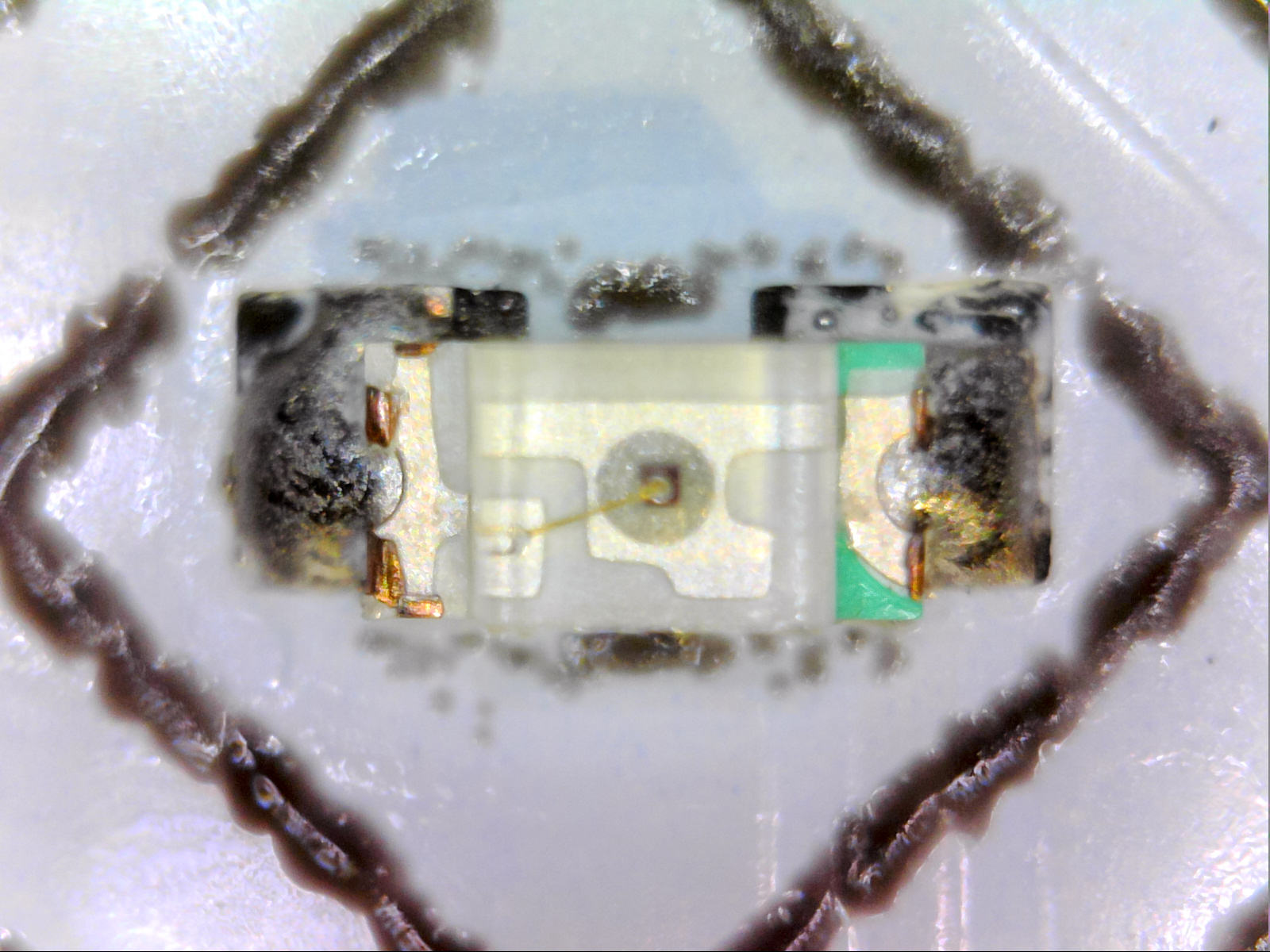
And here’s what they look like with the solder paste melted solid. Note that you don’t have to actually get the LEDs perfectly lined up when you’re using solder paste to do SMD soldering, if you’re slightly off then surface tension will (hopefully) pull them all into near perfect alignment.
I tried 0804 LEDs but they were too big to fit within the segments so I dropped down to 0603, which if you don’t know what that means, they’re 0.06 inches by 0.03 inches, or around 1.5mm by 0.76mm. This is 100% tweezer territory. Here’s a size comparison for you.

Hi I’m a tiny 0603 LED! These are my friends, a US penny and an Australian 5c coin!
Here’s what the circuit board looks like all lit up
(Youtube Link in case the above video doesn’t work for you)
Here’s what the final thing looks like with only one layer of diffuser over the top! It honestly could’ve been fine like this, but because I went the extra mile and made 2 diffuser layers, those segments are more evenly lit than the standard 7-segments I used for the normal digits!
(Youtube Link in case the above video doesn’t work for you)
Just because, this is what the digit circuit boards look like with a thermal camera, which is a great way to make sure that all the connections are good. This step certainly isn’t necessary, but I have access to a thermal camera with work, so I figured why not use it.
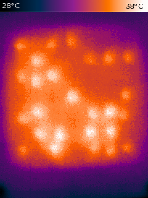
Thermal camera photo of a D’ni digit
Put this all together, and you get a finished 25-segment display module for showing D’ni digits! The screws are carefully positioned so the threads will go through the case but the head of the screws overlap the modules to hold them in place. Here’s what they look like – layered like an onion, or maybe an Ogre.
Overview of the layers of a 25-segment D’ni Display Module
Here’s what the insides look like without any wires connected. Bottom left in pink are some TLC5947 constant-current variable brightness LED drivers, and they’re sitting in standard off-the-shelf breakout boards with heatsinks attachedto them. These are what turn on/off all the LEDs behind the D’ni digits. Bottom right is some power supplies to convert the 9V in to the 5V some chips require (this takes some of the heat load off the TLC5947’s for the segments with only 1 or 2 LEDs in them).

The inside of my 25-hour D’ni clock, without any wires connected. The top right is a voltage level converter that I screwed up its size in the circuit board design step, so I just extended it up to have enough room to fix the error
Top middle is another custom circuit board with high-current shift registers to display the “normal” digits. This whole board was designed to be through-hole, as an “easy” design for a beginner solderer to start with. The reason why I’m using a bank of shift registers to control all the LEDs instead of just alternating between them in banks is that this means the display has no flicker and still works during high-speed/slow-motion photography experiments – which is part of what makes it a chronometer and not just yet another fancy clock. Rounding it off is the guts, a branded (not Chinese knock-off; they often have bad power regulators) WeMos/Lolin D1 Mini ESP8266. Having 802.11n-speed WiFi capabilities means it’s already equipped with a reasonably accurate Quartz crystal, to the point that I found an external timekeeping regulator like a temperature/oven based crystal to be unnecessary. The logic it runs isn’t too complicated – connect to the nearest available WiFi point, perform a geoIP lookup, perform a timezone lookup for that location, then poll a few of the nearest NTP servers every few hours. The initial sync is pretty much always within 3ms, and by keeping track of the ESP8266’s clock drift as well as the latency/jitter to the nearest NTP servers (plus a few additional tricks like time of day to estimate the crystal’s temperature variance and waiting for a quiet moment on the WiFi network before transmitting to reduce jitter), its accuracy is refined with each update. Internally it calculates its accuracy in picoseconds (that’s the unit prefix smaller than nanoseconds), but that’s mostly because I’ve been stung enough times by weird edge cases that I try to avoid floating-point maths wherever possible. Officially I’m only calling it accurate to within a best-case of 1ms because that’s a nice round number & is already beyond my home DIY abilities to measure or improve, and just to make extra sure I’m not “overselling” its accuracy that’s why the display only shows a 100ms & a 10ms digit, but not a 1ms digit. One hidden feature of this chronometer is because of the choice of drivers used for the LEDs, I can fully control their brightness and not just turn them on or off – for instance, at night the display dims and the squares around the D’ni digits turn off so it isn’t blindingly bright if you have to go to the bathroom at 2am.
These circuit boards are held up by custom 3D printed standoffs – sure, I could’ve just bought some, but 3D printing some was cheaper.

This design was very cheap and very modular, but its one problem was a ridiculous number of wires were involved – over 450 (!) connection points, all of which have to be connected to wires long enough that you’ve still got enough space to access them, which occasionally gives signal integrity flickers. If I was doing this again, I absolutely would design the digit circuit boards to at least have the shift registers included on them, to drastically reduce the number of potential failure points.


The final step was to laser cut a box to fit this all within. I used the fantastic online tool Boxes.py to make this happen – this is the “Display Case” option. All I had to do here was place holes for the displays & power cable, then get laser cutting. I recommend doing a small test first to make sure you get the play or burn correction settings right depending on how snug a fit you want. This also shows what the box actually looks like, since it’s so hard to photograph glossy black acrylic.

The warning label is true – lasers are awesome.
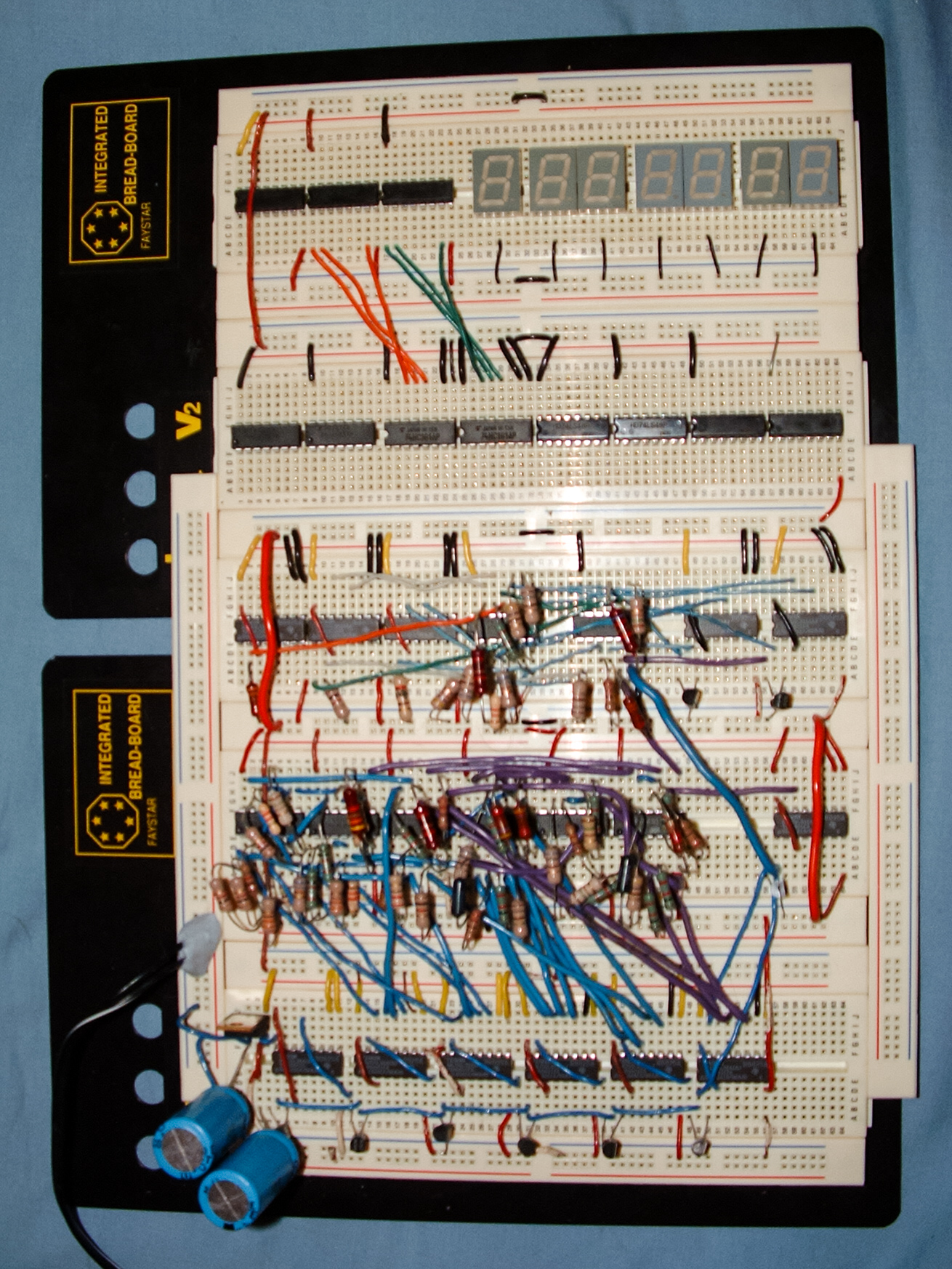
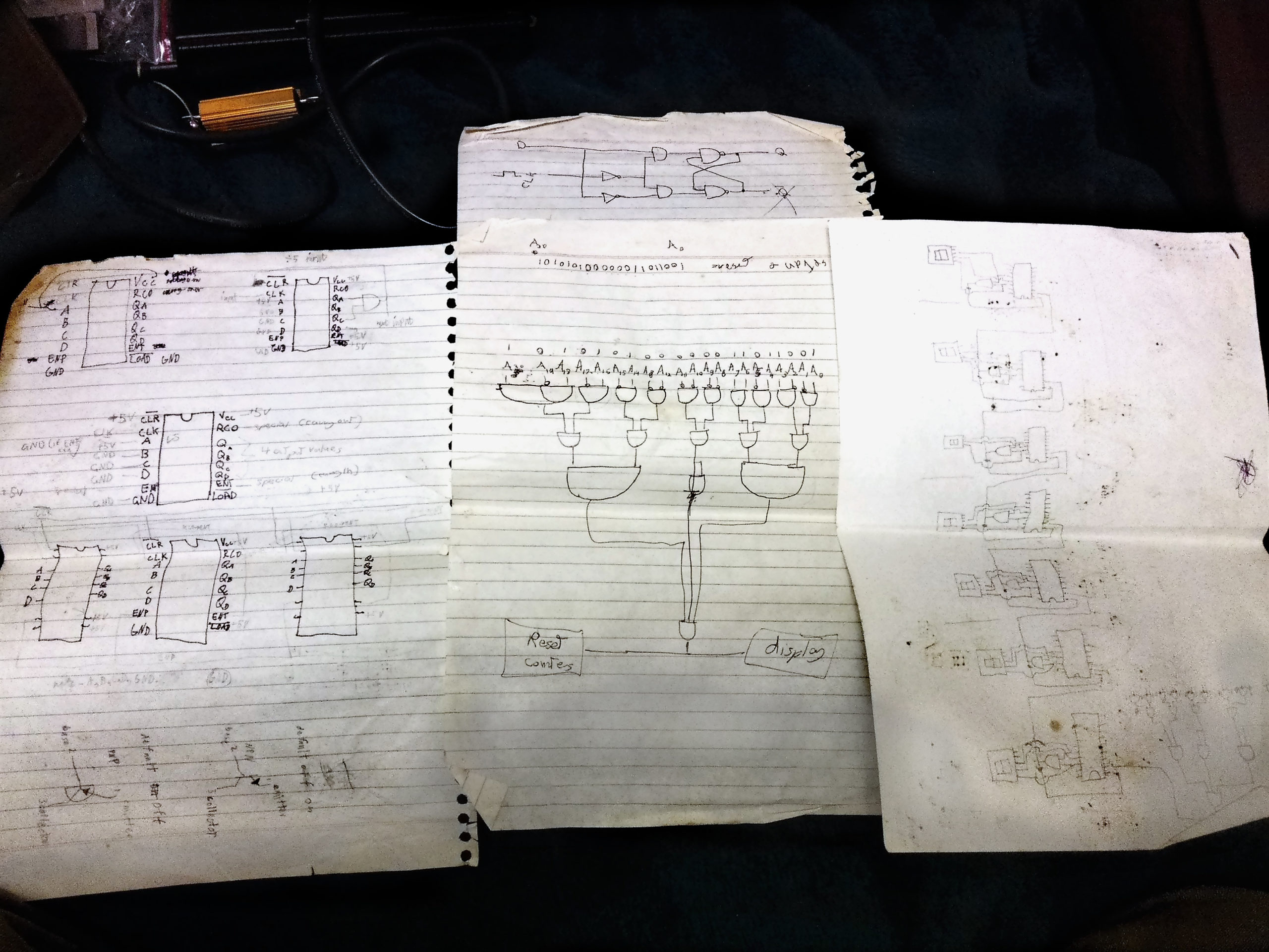
Oh and before I forget – don’t ever give up on your electronics projects just because they seem too hard. I started trying to build this clock nineteen years ago by trying to assemble it out of individual transistors, because modern cheap easy-to-use microcontrollers like Arduinos weren’t a thing, and higher-speed wireless-enabled ones like the ESP8266 were even further away. Building things with electronics is literally getting both easier and cheaper every single year. So if you think something is “too hard” right now, wait a few years and you’d be surprised what other options might be available for you! Here’s one of my failed attempts to build this project from back in 2002 (yes really that old!).
Finally, here’s the SVG of the D’ni Digits including segment numbers, and Gerber files of both the SMD 25-Segment D’ni Display Digit circuit boards and the through-hole normal digit shift register circuit board. You’re free to create whatever you want with these – just credit & link back to me plus let me know so I can see what cool stuff you make! I officially unveiled & presented this chronometer at Mysterium 2019, the annual fan convention for Myst fans. Here are my slides for the presentation, and you can watch my presentation below – I skip over some of the more technical areas but I go more into actual D’ni timekeeping than I do on here.
(YouTube link in case the above video doesn’t work for you)

One final final thing – just to show that the 10ms digit really works and isn’t just a random blur, here’s a slow-mo recording of it at 240fps.
(YouTube link in case the above video doesn’t work for you)
(Before anyone tries to correct me – yes I know there are technically 36 discrete light cells making up 26 controllable segments in these displays, neither of which are 25. But I asked myself “what will people search for when looking to find this project?”, and since D’ni numbers are base-25 that’s what people are likely to use, so that’s why I decided to call them 25-segment displays instead. So there. 😉 )
Similar Posts
Gehn’s Holographic Imager/Andotrope
For my secret project for Mysterium 2023, I’ve spent the past 8 months making a replica of one of Gehn’s...
Mad Scientist Knife Switch Extension Cord
There’s a running joke amongst my friends that I’m an actual time-travelling mad scientist – mostly because it’s more true...
Some time ago I was interested in making my own segment displays too and also found no sources about it. My plan was to revive and test the Soviet idea of 8-segment alphanumeric display, which could show Cyrillic, most Latin and numbers (IEL, Hourglass, Kiev display, alien digits, call it as you want). The problem was that I also had no idea about LED displays manufacturing. So I decided to experiment using a very cheap substitute of resin: a hot melt glue. That’s what I found:
1. I assumed that there will be a solid (cut) form (made of wood as I had no plotter nor 3D printing – everything by hand) and a liquid (solidifying) diffuser poured in and joining the PCB. This was a good idea and finding proper hot-melt glue is a trial and error.
2. If no hot-melt glue works, it is possible to mix two of them, e.g. too transparent with too opaque. The result is not linearly dependent on concentration and was slightly bent towards more opaque in my case.
3. Cooling rate has its impact on opaqueness.
4. Faster cooling rate – more blur. Because these displays uses parallel lines, sometimes they must be blurry to be readable.
5. If LEDs are visible too much, use more opaque layer and then more transparent layer applied quickly after.
6. In hot melt glue, temperature of typical application (in a glue gun) is too low to pour it in a form. Right after the good temperature to pour it in form there is a boiling temperature in which some fractions of it transform into bubbles which do not look nice in a display.
7. The SMD LEDs I had (a bit larger, with flat metal pins) caused troubles as they protruded, so were too visible through diffuser. OK, maybe using two for shorter and 3-4 for longer segments was too small number. Generally: I drilled a hole in PCB and clogged it with LED, LED lights through the hole into cell, and is soldered on the back side.
My experiments ended with 1 (one) character 8-segment display which I tested and got the conclusion that I need to read it from a distance and characters have to be large.
Very nice! Can you make a Nixie tube version? I will let you nut inside me!